01 / START AT THE SERVER
Two power supplies can feed one server
Some servers have two power supply units (PSUs). One can connect to rack PDU A and the other to rack PDUB. Both supplies feed the same server, so losing one input may not stop it.
That continuity depends on the server supporting redundant power operation, the remaining PSU and path being healthy, enough capacity remaining, and no shared dependency failing at the same time. It is a possible design behavior, not a guarantee from seeing two cords.
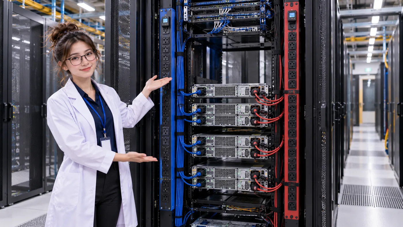
PATH A PDU A
- PDU A
- PSU A
PATH B PDU B
- PDU B
- PSU B
THE SERVER IS ONLY THE ENDPOINT
Two PSUs are only the start of the story
A second PSU cannot protect a server from a failure that removes both upstream feeds. To understand A/B power, follow each connection backwards through its PDU, UPS, and facility distribution. The goal is for a failure in one power train not to remove the other path unnecessarily.
02 / FOLLOW BOTH POWER TRAINS
A and B should be traceable paths
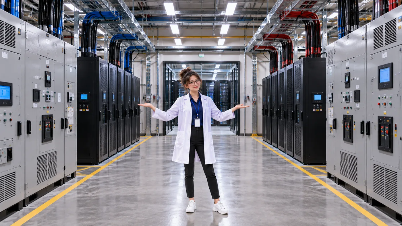
A simplified design might route Path A through one source and distribution train into UPS A, PDU A, and PSU A. Path B reaches UPS B, PDU B, and PSU B through another train. Both meet at the server’s power supplies.
Facilities use many topologies. These lanes describe a way to reason about dependencies; they do not prescribe one universal data center design.
If the upstream labels are new, revisit Utility Power & Switchgear to trace where facility power enters and how its major paths are managed.
PATH A
- Source / distribution A
- UPS A
- PDU A
- PSU A
PATH B
- Source / distribution B
- UPS B
- PDU B
- PSU B
LOOK UPSTREAM
What does “independent” really mean?
Independence is not established just by counting cables, PDUs, or UPS cabinets. Ask instead:which dependencies do the two paths share? Shared equipment can exist at several points in the chain:
A shared item is not automatically a defect. Its role, failure modes, and impact on the required service need to be understood in context.
03 / FIND THE SHARED DEPENDENCY
Two paths can still share one failure point
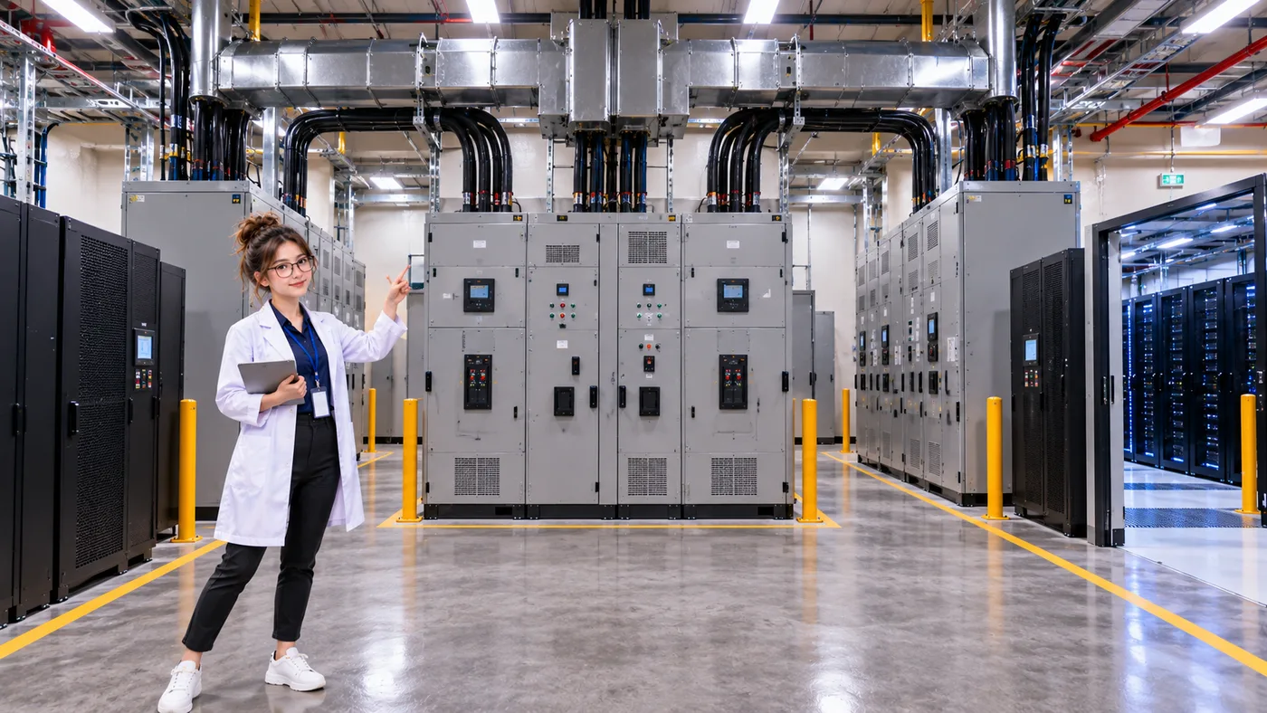
The paths below look separate downstream, but both UPS units rely on one shared upstream distribution component. If that shared component fails, both paths may lose their source. That shared dependency can be a Single Point of Failure (SPOF) for the service being protected.
COMPARE THE DEPENDENCIES
Separate upstream feeds can improve independence
PATH A
- Source / distribution A
- UPS A
- PDU A
- PSU A
PATH B
- Source / distribution B
- UPS B
- PDU B
- PSU B
A USEFUL DISTINCTION
Redundancy is more than duplication
Duplication
“There are two of something.”
Redundancy
“The system can tolerate the intended failure and continue the required service.”
Two devices are not useful redundancy if the same failure disables both or the survivor cannot support the load that must remain online.
04 / CHECK THE CAPACITY
An available path also needs enough capacity
In normal operation, load may be divided or assigned across both power paths. If Path A fails, Path B must have enough available capacity for the load and service the design is required to retain. A healthy-looking second path is not sufficient if it cannot carry that surviving demand.
01 Normal operation
Path A and Path B supply their assigned share of the load.
02 Path A unavailable
The surviving Path B must support the load the design intends to keep online.
THREE CAPACITY LABELS
N, N+1, and 2N—at a defined level
- N
- The capacity required to support the intended load.
- N+1
- That required capacity plus one additional unit or component at the level being discussed.
- 2N
- Two full N-capacity systems or paths at the defined level.
These labels describe capacity arrangements; they do not prove resilience on their own. Topology, dependencies, operating conditions, maintenance states, and failure scenarios determine what service can actually survive.
05 / REASON THROUGH A FAILURE
What happens when Path A fails?
Start with both paths healthy and the server operating. Then imagine Path A is unavailable. Rather than assuming the answer from an A/B label, trace the service through a few checks:
- IndependenceIs Path B separate from the component that failed?
- AvailabilityIs Path B healthy and able to deliver power?
- CapacityCan Path B carry the load the design must retain?
- IT endpointCan the server continue on its surviving PSU and feed?
A REPEATABLE WAY TO THINK
When testing redundancy, ask
- What failed?
- What depends on it?
- What else shares that dependency?
- What path remains?
- Does the remaining path have enough capacity?
- Does the required service remain available?
POWER 101 · COMPLETE
You now understand the basic data center power path
Follow the chain you have built across the previous lessons, with a generator as an alternate source within the facility’s resilience design:
- Utility
- Switchgear
- UPS
- PDU
- Server
And now you know the more important question: What happens when one part fails?
THREE THINGS TO REMEMBER
Trace the paths before trusting the labels
- Two power connections do not automatically mean two independent paths.
- Redundancy needs independence and enough surviving capacity.
- Trace dependencies upstream before deciding whether a design can tolerate a failure.
POWER 101 · COMPLETE
Next, begin Network 101
Power 101 followed the question, “Can the server remain powered?” The next chapter starts with another dependency: “Can the server communicate?” Meet the network switch in Lesson 01.
Start Network 101 · Network Switch →LEARN → CONNECT → FAIL → VERIFY
Now break the power path
Put the reasoning into practice. Start by building a dual path, inspect a shared dependency that defeats apparent redundancy, then test a defined set of component failures and surviving capacity.
Build a second utility → UPS → PDU path and test UPS-A failure against the rack load.
Trace both UPS input chains to the shared switchboard, diagnose it, and separate the source paths.
Test the required UPS-A, UPS-B, PDU-A, and PDU-B loss cases against service and design intent.