01 / WHERE POWER ENTERS
A data center starts with an incoming source
Most facilities normally receive electricity from an external utility or grid connection. Before that power reaches IT equipment, facility infrastructure routes it and makes it suitable for the site’s distribution design. This upstream side may include a utility service, substation, transformers, incoming switchgear, distribution equipment, and metering or protection systems.
The exact arrangement differs by country, utility service, facility size, and engineering design. The image shows the scale of equipment that can sit between the grid and the familiar server room.
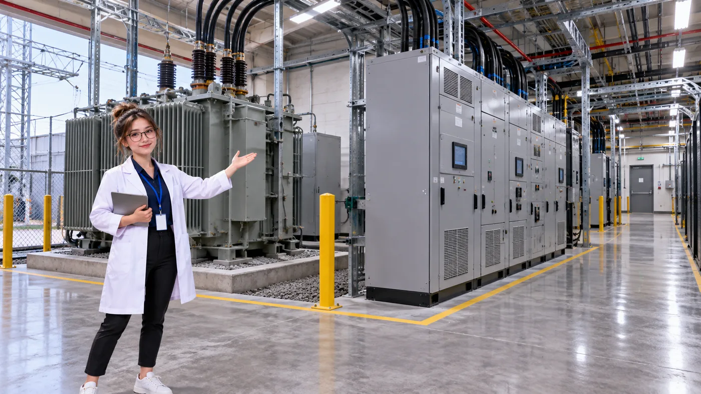
A CHANGE IN VOLTAGE
What does a transformer do?
A transformer changes alternating-current voltage from one level to another. A facility may receive power at a voltage different from the one used by downstream equipment, so transformers can adapt the supply as the facility design requires. There is no single voltage level that applies to every data center: utility service, country, and distribution architecture all matter.
02 / MEET THE SWITCHGEAR
A lineup that manages major electrical paths
Switchgear is an assembly of electrical devices used to operate and protect power circuits. It can be a row of cabinets containing breakers, controls, instruments, and shared conductive bus structures. Its main jobs are related, but distinct:
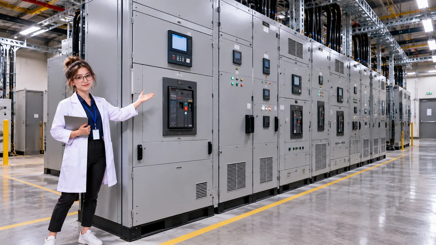
Switching
Connect or disconnect electrical paths.
Protection
Interrupt abnormal electrical conditions when the protection system calls for it.
Isolation
Separate an appropriate section for maintenance or fault management.
Distribution
Direct power toward downstream facility systems.
WHAT IS INSIDE?
Switchgear is more than a big switch
Depending on its purpose and design, switchgear can combine circuit breakers, disconnecting or isolation devices, protective relays, metering, controls, bus structures, and monitoring. A circuit breaker can interrupt a circuit when commanded or when protection logic operates. Settings, device types, and operating logic determine how that happens; it is not simply a switch that reacts to every problem in the same way.
These assemblies work as part of a coordinated electrical system. Their configuration depends on the facility, so one photograph cannot describe every installation.
Four jobs, one managed power system
- SwitchOperate a power path
- ProtectRespond to abnormal conditions
- IsolateSeparate a section appropriately
- DistributeFeed downstream systems
03 / CONNECT THE POWER SYSTEM
Now follow power all the way to a server
You have met the individual pieces. Here is one simplified mental model that connects upstream facility power to the IT load. In normal operation, utility power passes through incoming distribution and switchgear, then through a UPS and PDU before reaching a server.
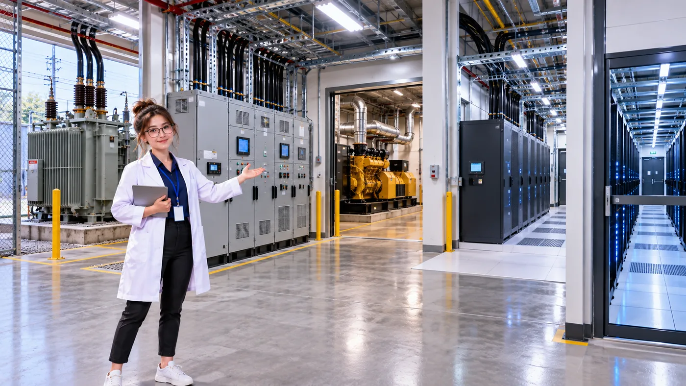
Normal utility path
- Utility / grid
- Transformer / incoming distribution
- Switchgear
- UPS
- PDU
- Server
Generator-backed path
- Backup generator
- Transfer / switching architecture
- UPS
- PDU
- Server
WHEN THE NORMAL SOURCE IS LOST
Normal power and backup power have different jobs
Normal operation
Utility → switchgear and distribution → UPS → PDU → server.
Utility outage
The UPS initially supports its protected load. A generator starts; when its source is available and connected through the facility’s transfer and distribution design, the UPS can continue protecting its downstream load.
A generator needs a startup and connection sequence. The UPS helps maintain continuity during that transition and continues its designed power-conversion and protection role. Read more in What Is a UPS in a Data Center? and What Is a Backup Generator in a Data Center?.
UPSTREAM AND DOWNSTREAM
Where does the PDU fit?
Switchgear manages major facility power paths much farther upstream. A PDU distributes power closer to IT equipment. In the simplified chain, power passes through switchgear, the UPS, and then a PDU on its way to a server. They solve different problems and are not interchangeable terms.
Switchgear
- Upstream facility infrastructure
- Switching and protection
- Isolation and major distribution
PDU
- Downstream distribution toward IT loads
- Often close to rack equipment
- Distributes power according to its installation
“PDU” can describe equipment at different scales. This comparison focuses on the rack-level concept introduced in the PDU beginner lesson.
04 / TRACE THE DEPENDENCIES
A downstream path depends on what feeds it
If a breaker opens and interrupts a path, equipment downstream that depends only on that path may lose its upstream source. Service can continue when an appropriate alternate path exists and is available with enough capacity. The wiring and transfer design decide whether it can actually help.
Two UPS units can look like two paths, yet still depend on one shared upstream component. If that shared component fails, both paths may be affected. The next lesson explores A/B Power & Redundancy and why two paths do not automatically mean two independent paths.
- Utility
- Switchgear
- UPS
- PDU
- Server
THREE THINGS TO REMEMBER
Keep the upstream picture in mind
- Utility power enters through facility infrastructure. The exact equipment and voltages depend on the site.
- Switchgear manages major electrical paths. It can switch, protect, isolate, and distribute power.
- Downstream equipment depends on its upstream feed. That is why path capacity and independence matter.
LEARN → CONNECT → SIMULATE
Now build the power path
In Build Your First Data Center, start with an empty room and connect the modeled utility → UPS → PDU → rack hierarchy. Then explore a utility outage, battery support, and generator transfer in the failover lab.