01 / MEET THE BACKUP GENERATOR
Facility-scale power for a longer outage
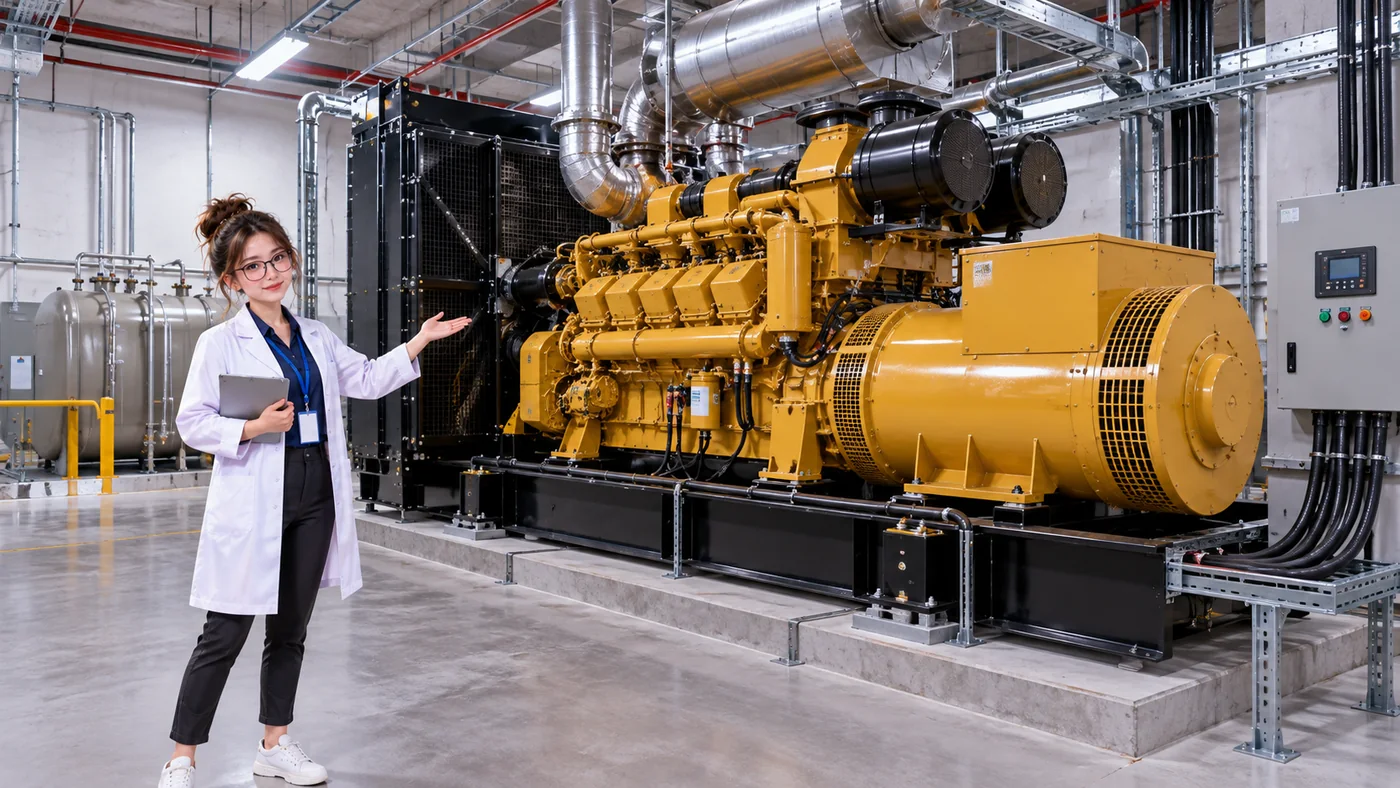
A standby generator converts energy from a fuel or other designed source into electrical power. Data centers may use generator sets as an alternative source when utility power is unavailable. This is building infrastructure, often a substantial engine and alternator assembly—not a portable household generator.
The people and equipment in this image give a sense of scale. A generator must be selected and operated for the loads its system is meant to support; the available output, startup behavior, and facility connections all depend on the design.
TWO COMPLEMENTARY ROLES
The UPS bridges; the generator becomes another source
A UPS can support protected loads without waiting for a mechanical engine to start. A standby generator needs a startup sequence before its electrical output is ready to connect. In many designs, the UPS supports the protected load during that transition, and generator-backed power can then supply its upstream input.
- Utility fails
- UPS supports protected load
- Generator starts
- Generator-backed source becomes available
- UPS continues protecting load
02 / HOW DOES A GENERATOR MAKE ELECTRICITY?
Fuel energy becomes electrical output
A generator set changes energy in a few understandable stages. The exact equipment and fuel depend on the installation, but the basic idea is fuel powering an engine that turns an alternator.
- Fuel
- Engine
- Mechanical rotation
- Alternator
- Electrical power
- Fuel
- Stores chemical energy for the engine to use.
- Engine
- Converts fuel energy into mechanical rotation.
- Alternator
- Converts that rotation into electrical energy.
- Electrical output
- Feeds the facility system through the appropriate distribution and control equipment.
MORE THAN THE ENGINE
A generator set depends on supporting systems
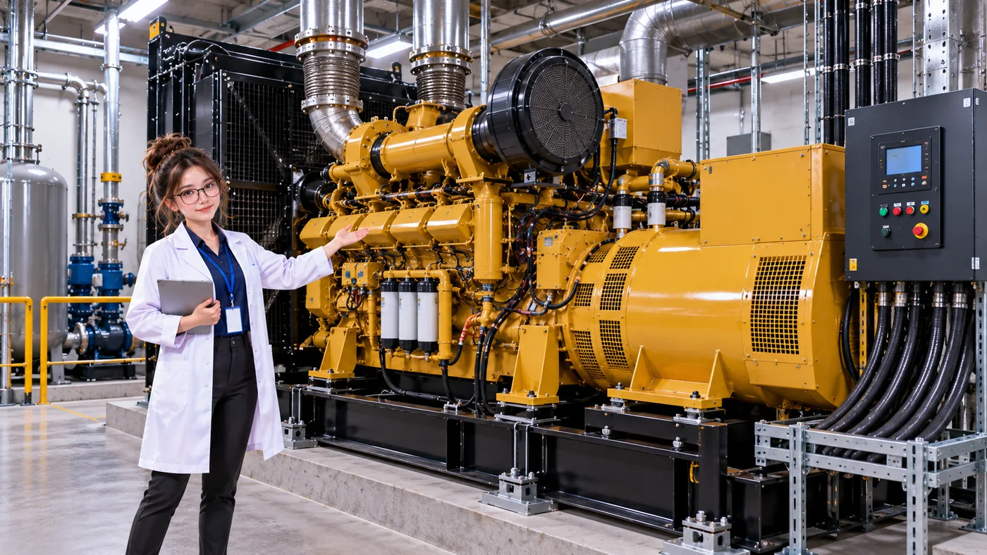
The engine and alternator are only part of a standby power installation. The specific arrangement varies, but common supporting systems include:
- Fuel systemStores and delivers the fuel the equipment is designed to use.
- Starting systemStarting batteries or another mechanism helps crank the engine.
- Cooling and heat rejectionManages engine heat, sometimes with a radiator or another cooling arrangement.
- Exhaust and ventilationRoutes exhaust and provides the airflow the installation requires.
- ControlsMonitors conditions and coordinates starting and operating states.
- Electrical outputConnects through suitable protection, transfer, and distribution equipment.
These systems have to work together. Their location, configuration, and operating limits are specific to the facility and generator design.
A USEFUL DISTINCTION
Engine vs. alternator
Engine
Uses fuel to produce the mechanical rotation that drives the set.
Alternator
Converts the engine’s mechanical rotation into electrical power.
In everyday speech, people often call the whole assembly “the generator.” The installed generator set also relies on its starting, cooling, exhaust, controls, and electrical systems.
03 / WHAT HAPPENS WHEN UTILITY POWER FAILS?
The generator joins a system that is already protecting the load
After utility power becomes unavailable, the UPS energy storage can support protected IT loads while the generator starts. The engine runs the alternator; voltage and frequency reach acceptable conditions; then facility transfer and distribution controls make a generator-backed source available according to the site design. The UPS can then have an upstream source again while continuing to protect its output.
- Utility healthyNormal input supplies the facility system.
- Utility failsThe normal electrical source is interrupted.
- UPS holds loadEnergy storage supports protected output.
- Generator startsThe generator receives a start command and the engine begins its startup sequence.
- Generator stabilizesOutput reaches conditions accepted by the facility design.
- Generator-backed source is connectedTransfer and distribution controls make the source available.
- UPS has an upstream sourceThe UPS continues supporting and protecting its output as designed.
- Protected load continuesServers remain supplied through the transition.
This sequence is a beginner’s mental model, not a universal switching procedure. Facility architectures, control sequences, redundancy arrangements, and actual timing vary.
CONNECT THE COMPONENTS
See the generator in the wider power path
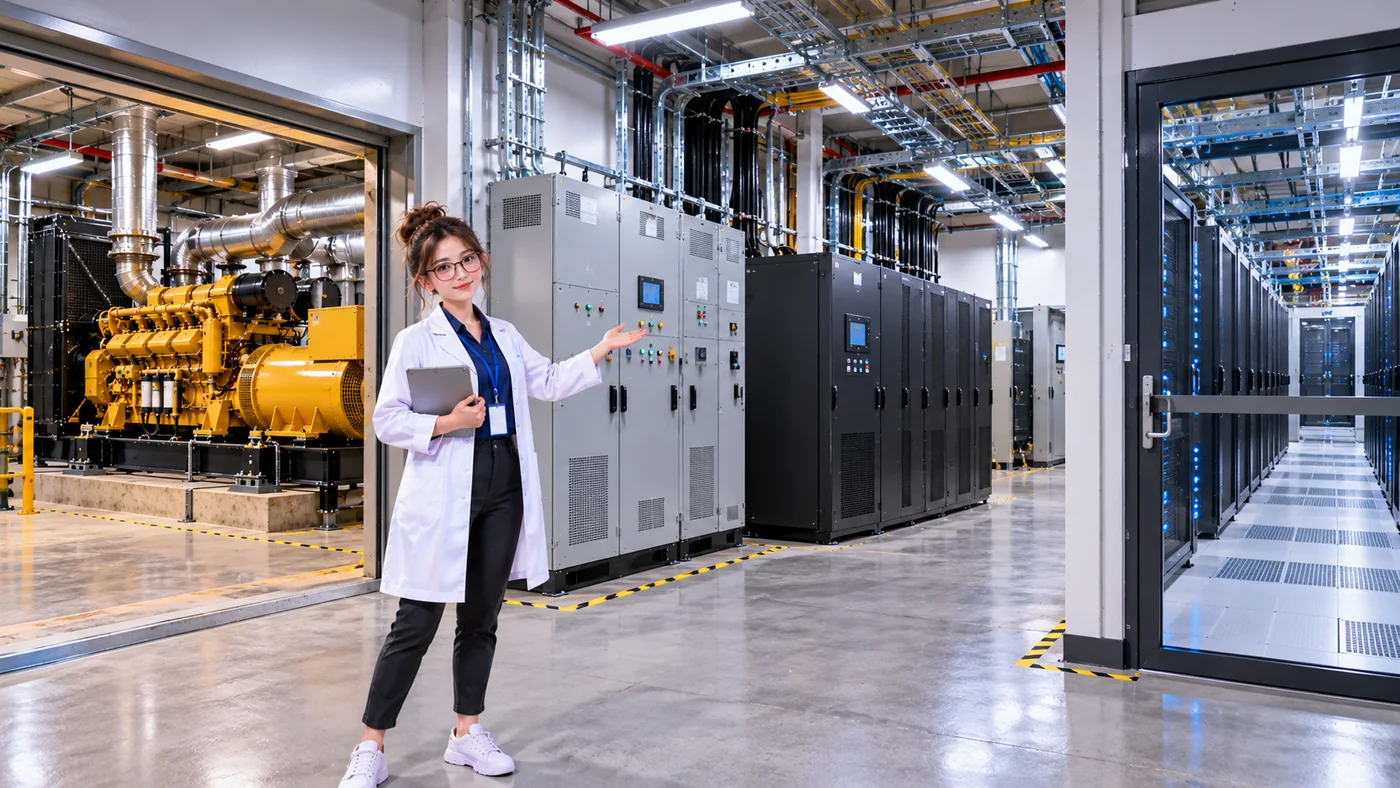
In a simplified normal path, utility power feeds electrical distribution and the UPS, followed by a rack PDU and the server. During an outage, a generator-backed source may feed that distribution system so the UPS can continue supporting its protected output.
Normal utility supply
- Utility
- Electrical distribution
- UPS
- PDU
- Server
Generator-backed supply
- Generator
- Electrical distribution
- UPS
- PDU
- Server
These are simplified paths for learning. Real facilities may include transformers, switchgear, automatic or static transfer systems, multiple generators and UPS units, redundant buses, bypass arrangements, and A/B paths.
For the equipment immediately downstream, revisit the PDU lesson and Server lesson.
WHY NOT RUN ON GENERATOR ALL THE TIME?
Standby generation is one part of the resilience plan
Where utility service is available and the facility is designed to use it as the normal source, standby generators are kept for backup operation. Running them introduces fuel, maintenance, mechanical wear, emissions, operating constraints, and testing requirements. Site designs and operating policies vary, so this is not a rule for every installation.
HOW LONG CAN A GENERATOR RUN?
Backup duration depends on fuel and operations
A generator does not provide unlimited backup power. How long it can operate depends on available fuel, generator load and fuel consumption, equipment condition, fuel-delivery logistics, facility design, and operating constraints. Refueling assumptions and fuel arrangements are part of the site’s resilience plan.
A FIRST LOOK AT CAPACITY
The available output must support the assigned load
A generator needs adequate capacity for the electrical load it is expected to carry. If the required load exceeds available output, a facility may need multiple generator sets, prioritized or staged loading, load shedding, or other operating strategies. This is why it matters to trace both the source and the load when you evaluate a backup power path.
A FIRST LOOK AT REDUNDANCY
What if a generator fails?
Critical facilities may use multiple generator sets, capacity redundancy such as N+1, more than one electrical path, or fuel and operating arrangements designed for specific contingencies. Testing helps reveal how the installed system behaves. Multiple generators alone do not guarantee resilience: shared dependencies or insufficient remaining capacity can still interrupt service.
DataCenterTwin’s N-1 Resilience lab explores a defined set of UPS and PDU distribution failures and surviving-path capacity. Its current scope is not a generator-specific failure study.
KEEP THESE IN MIND
Three things to remember
- A standby generator can provide another source during a longer utility outage.
- The UPS bridges the startup and transfer period while generator-backed power becomes available.
- A generator depends on more than its engine: fuel, starting, cooling, exhaust, controls, and electrical distribution all matter.
LEARN → UNDERSTAND → CONNECT → SIMULATE → STRESS-TEST
Now simulate the failover
In the UPS Battery & Generator Failover lab, observe a utility interruption, battery support, generator startup, generator load acceptance, and protected service continuity in the model. Try changing transfer and stored-energy settings to see how the simulated system responds through the transition.