01 / MEET THE CDU
The bridge between two cooling loops
CDU means Coolant Distribution Unit. In many direct-to-chip designs, it circulates coolant through the technology or server-side loop and transfers heat to a separate facility loop.
A CDU commonly includes a heat exchanger and may also have pumps, valves, sensors, controls, filters, and fluid-management components. Depending on the design, it may monitor flow, temperature, pressure, alarms, and operating state. CDUs do not all use the same internal arrangement.
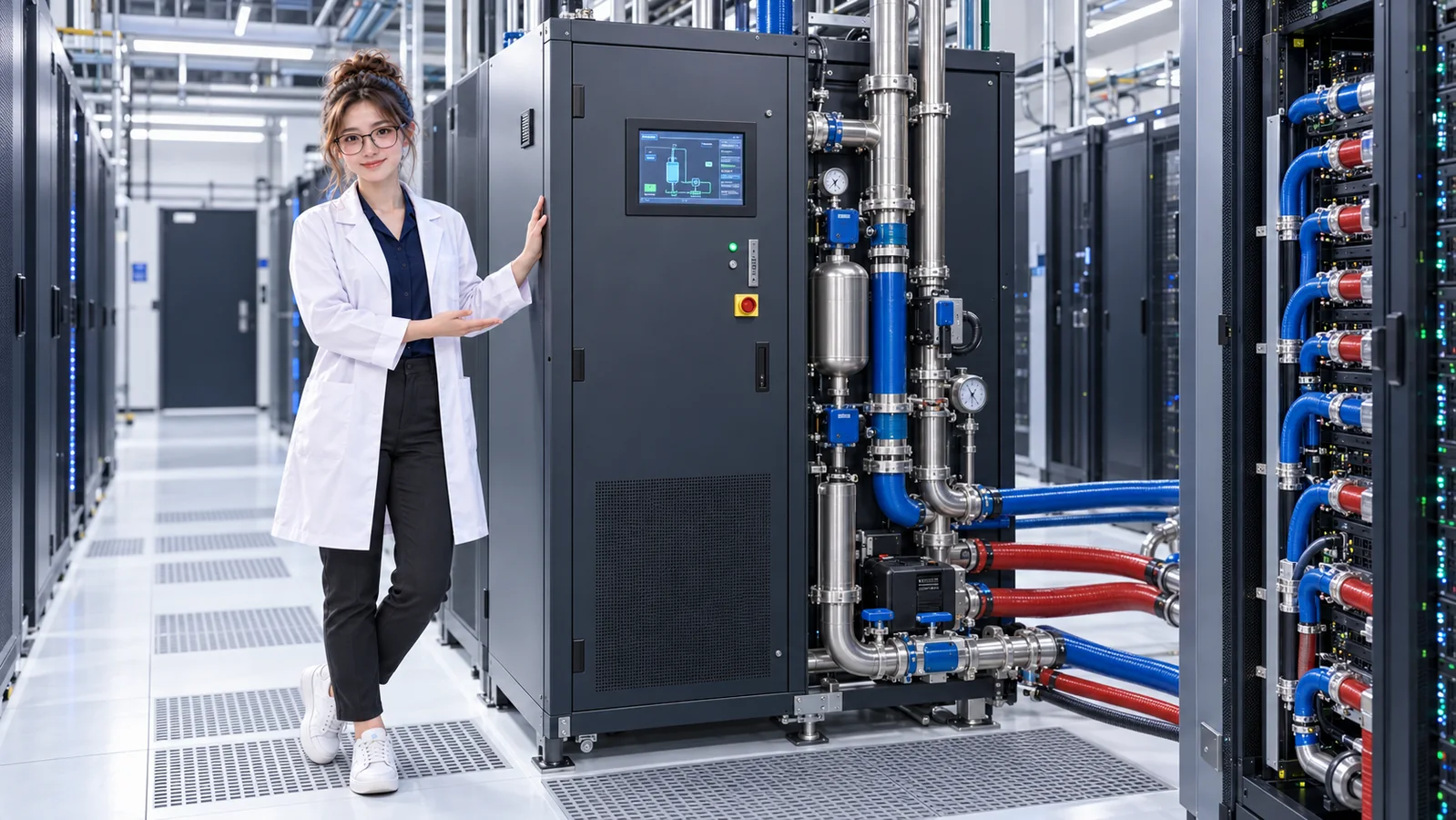
- CPU / GPUProduces heat
- Cold plateReceives chip heat
- Server liquid linesCarry coolant
- Rack manifoldDistributes supply and return
- CDUTransfers heat between loops
- Facility coolingCarries heat toward rejection
TWO LOOPS · ONE HEAT PATH
Why separate the rack coolant from facility water?
The technology loop typically serves server cold plates, rack manifolds, and equipment-side liquid connections. The facility loop typically serves building cooling infrastructure and carries heat toward plant-side removal. In many architectures, the CDU is a controlled boundary between them.
Keeping loops separate can help address coolant compatibility, cleanliness, pressure and temperature control, operational isolation, equipment protection, and maintainability. The right reasons and configuration depend on the installation.
Technology / secondary loop
- Coolant supply to servers
- Cold plates absorb chip heat
- Rack manifold gathers warmer return
- CDU circulates and conditions the loop
Facility loop
- Facility water reaches the CDU
- Water receives heat at the exchanger
- Warmer return leaves toward the plant
- Heat-rejection equipment carries heat away

Actual piping topology varies. A photograph cannot establish which connection is supply or return, or prove the exact loop design.
02 / INSIDE THE BOUNDARY
The heat crosses; the fluids may stay separate
A heat exchanger lets warmer technology-loop coolant transfer heat to the facility water across a physical boundary. The two fluids do not necessarily mix. Pumps move coolant around their respective paths; valves and controls may regulate operation, while sensors provide signals such as flow, temperature, and pressure.
Technology loop
Warm return from rack
CDU heat exchanger
Cooler supply back to cold plates
Facility loop
Cooler facility water to CDU
Receives heat
Warmer return toward heat rejection
FOLLOW SUPPLY AND RETURN
Each loop has a supply path and a warmer return
Technology loop
Cooler supply → cold plates absorb heat → warmer return → CDU
Facility loop
Cooler facility water → CDU receives heat → warmer facility return → plant / heat rejection
“Cooler” and “warmer” describe the direction of heat transfer, not a universal setpoint. Actual temperatures depend on the server equipment, CDU, facility design, and operating conditions.
Flow
Is enough coolant moving through the loop?
Temperature
Are supply and return conditions within the intended range?
Pressure
Is the loop operating within its intended hydraulic conditions?
CDU controls and monitoring may use these signals to help operate and protect the system. A single reading is only part of the picture; the readings and service outcome need to be considered together.
03 / THE COMPLETE PATH
Trace chip heat all the way to rejection
The CDU is a bridge, not the final destination for heat. IT power becomes heat; the cold plate and technology coolant carry it away from the chip, and the facility system must carry it onward to heat-rejection infrastructure.
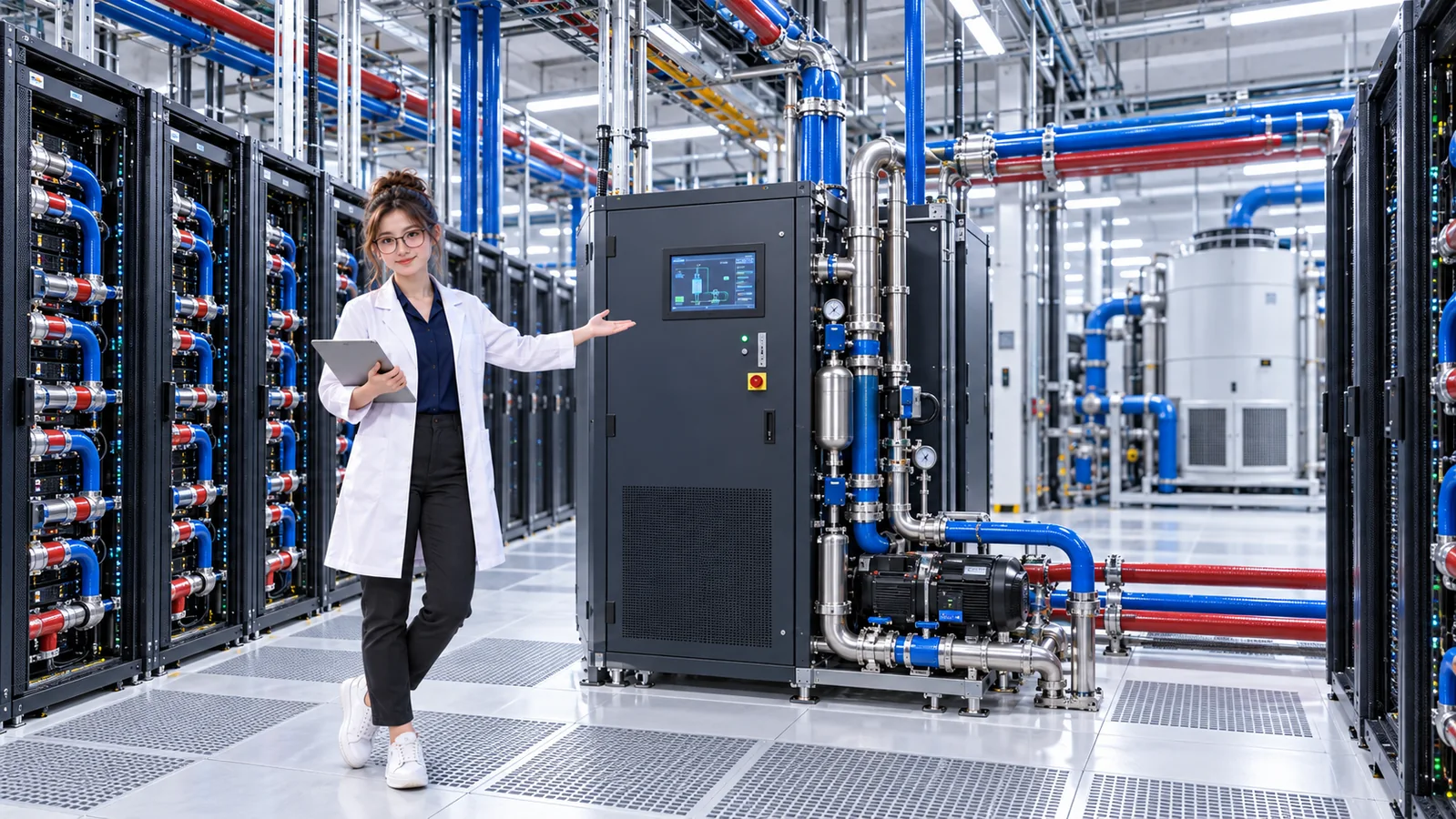
- CPU / GPUIT power becomes heat
- Cold plateTransfers chip heat
- Secondary coolantCarries heat through server loop
- Rack manifoldConnects server branches
- CDUHeat exchanger transfers heat
- Facility waterCarries heat from CDU
- Facility coolingMoves heat onward
- Heat rejectionChiller, dry cooler, or other system
IT power → chip heat → cold plate → technology coolant → CDU → facility loop → heat rejection.
Cooling is the work of transporting heat. Actual facilities may use a chiller, dry cooler, or another heat-rejection arrangement; not every site uses the same one.
FAILURE THINKING
What can happen if a CDU or liquid path fails?
If a CDU fails or liquid flow is reduced, less heat may leave the affected equipment. Component temperatures can rise over time, and service may eventually be affected. The sequence and timing depend on redundancy, controls, thermal inertia, rack load, alternate cooling paths, server protection behavior, and facility design.
- IT load continuesHeat is still produced
- CDU fails / flow reducesLiquid path is constrained
- Heat removal fallsLess heat leaves the rack
- Temperature may riseThermal margin can shrink
- Protection may respondDemand can be reduced
- Service may be affectedDepends on surviving paths
A running pump alone does not prove that the heat exchanger is rejecting heat. Follow the path from cold plate through CDU to facility water, then check temperature and service recovery over time.
PUT THE FAILURE PATH IN CONTEXT
Diagnose a CDU failure in DataCenterTwin
In the CDU Failure Diagnosis lab, observe CDU-A loss, identify the initiating fault, author a restore event after the fault, and verify cold-plate and service recovery from 90 seconds onward. Check that recovery persists through the evaluated window; a running pump or low demand alone does not prove the heat path is restored.
THREE THINGS TO REMEMBER
Keep the boundary and the heat path in view
- The CDU connects the technology coolant loop with the facility loop in many designs.
- The heat exchanger transfers heat; the fluids may stay separate.
- Heat still needs a path from the chip to the facility’s heat-rejection system.
Continue with Liquid Cooling Basics · Lesson 06, or return to Why Data Centers Need Cooling · Lesson 01 to revisit the core idea: cooling transports heat.
PASS IT ON